


Geometric dimensioning and tolerancing
ISO-ASME/GD&T with coordinate techniques
Course aims:
- Proper interpretation of measurement results
- Thorough knowledge of the differences between ASME and ISO standards
- Acquiring skills of designing and optimizing the process of manufacturing goods
- Knowledge in the field of Coordinate Measuring Technique and the available measuring instruments
Course type
Course level
Duration
Prerequisites
Location
See the laboratory
Dates
Schedule
day 2 h. 9.00 - 16.00
day 3 h. 9.00 - 16.00
Price
Highlights
- A certificate of completion
- Educational aids: scripts
- Access to specialist magazines and technical literature (regarding stationary training)
- Writing aids (pen, notebook) - regarding stationary training
- Complete care of idividually assigned customer service person
- Participant Cards with discounts to partner restaurants / pubs in Gliwice (regarding stationary training)
Catering
More information
Contact
Closed trainings
Certificate
More information
Accommodation
Please contact us on:
0048 32 4111 000
info@emt-systems.pl
should you have any questions on the course you have chosen
Course program
- Standardization in engineering drawing:
- According to the American standard ASME Y14.5-2009
- According to the requirements of the ISO GPS system – international standards
- Classification of dimensions. Dimensioning tolerances. General tolerancing.
- Tolerance and interference fit
- Dimension chains and operations on toleranced dimensions
- Classification and structure of GPS standards (Geometrical Product Specification).
- Overview of the basic terms used in both standards
- Division and classification of geometrical tolerances
- Structure of ISO and ASME standards
- Symbols and basic modifiers
- Rules for interpretation of requirements for geometrical tolerances.
- Independence principle according to ISO
- Rule #1 – „Perfect form At MMC”
- Dimension interpretation
- Maximum material requirement (M), least material requirement (L) and reciprocity requirement (R).
- The border of maximum and least material requirement
- Virtual condition for maximum material requirement
- M, L and R modifiers
- Shape tolerances.
- Methods of evaluating deviations of shape
- Straightness, flatness, circularity and cylindricity tolerances
- Coating requirement and shape tolerance
- Bases.
- Symbols, position of the symbol base, bases – RFS requirement, bases – MMC requirement
- Partial bases.
- Direction tolerances.
- Perpendicularity, parallelism and angularity tolerance
- Maximum material requirement with dimension tolerances
- Geometric tolerances.
- Position tolerances: point position tolerance, line position tolerance, element array position tolerance, tolerancing by compound tolerances and combined tolerances
- External tolerance limit
- Concentricity and alignment tolerance, symmetry tolerance
- Free state tolerancing and others
- Shape tolerances for the determined outline or surface.
- Shape tolerances of the defined outline
- Shape tolerance of the defined surface
- Run-out tolerances.
- Radial and axial run-out tolerances
- Run-out tolerances in the defined direction
- Total run-out tolerances
- Overview of the differences between ASME and ISO standards.
- Used symbols
- Differences in terms and symbols
- Practical exercises- participants make sketches and calculations in the following areas:
- Examples of specifying requirements on technical drawings. Interpretation of records, calculating resultant and adjustment dimensions
- Principle of coating – verifying compliance/non-compliance of products in case of the selected examples
- Shape tolerance of the defined surface – selecting proper tolerance records
- Maximum material limit – MML calculations
- Maximum material principle – analysis of examples and applications
- Tolerance components analysis
- Analysis of geometric deviations for the selected examples
- Analysis of the examples of constructions and technical drawings
- Problem shooting and doing exercises in groups, discussion
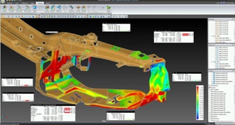
- Introduction to the Coordinate Measuring Technique
- Tools used in the Coordinate Measuring Technique (classification/application/accuracy).
- Basic rules in coordinate metrology
- Measurements of regular geometry and measurements of free surfaces
- Nominal/real/observed/associated geometry – methods of interpretation and occurring deviations
- Coordinate Measuring Technique in measurements of general and geometrical tolerances
- Preparing measurements on the Coordinate Measuring Machine - selection of a stylus module – qualification – definition of the coordinate system
- Basics of measurements on the coordinate measuring machine
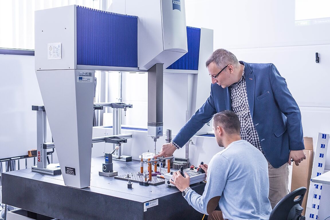
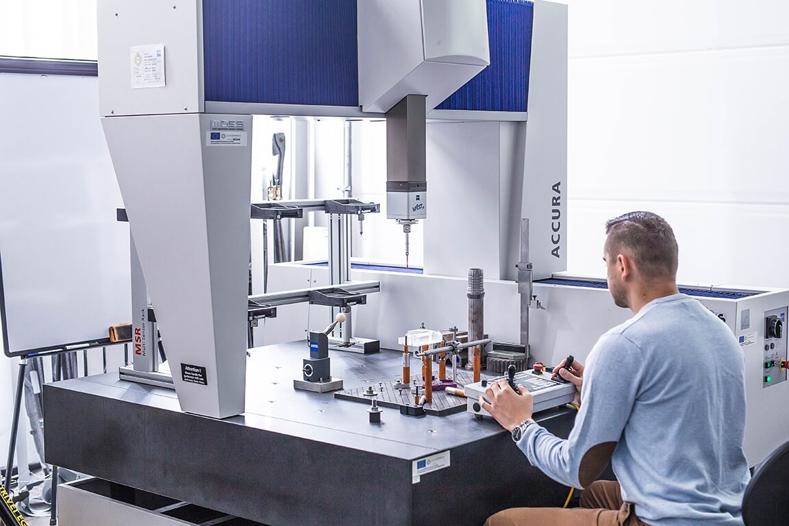
Laboratory
Classrooms and laboratories are air-conditioned, large and spacious. Workstations for the participants have been fitted with specialist equipment. The participants have at their disposal tools used in the industrial metrology and additionally - a coordinate measuring machine and measuring arm.
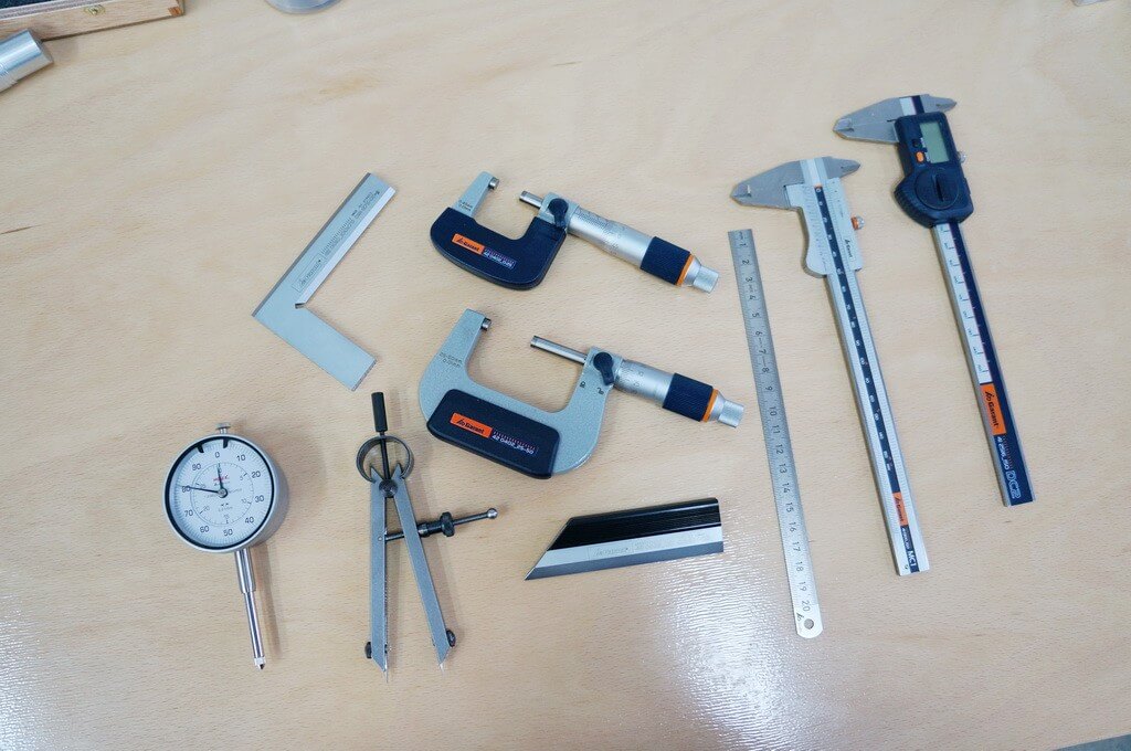
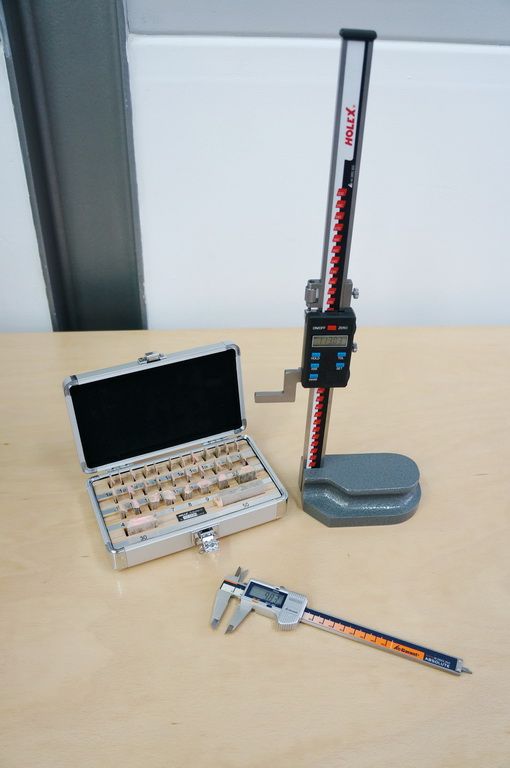
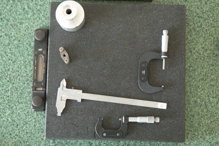
Measuring tools
Participants of the training course have at their disposal the following tools: calipers, micrometers, altimeters and measuring balls.
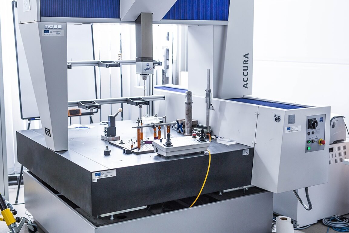
Coordinate measuring machine
ZEISS ACCURA coordinate measuring machine Characteristics of the performed measurements:- measurement range of the device: 900x1200x700mm
- measurement uncertainty MPE_P=1.7um
- faster selection of the optimal solution and saving of costly retooling of the machine thanks to using the MASS system (Multi Application System Sensor)
- MASS allows using both active scanning central head, heads that can be mounted in the tilting rotary joints with passive scanning head, as well as optical scanning heads
- It features scanning measuring head Zeiss VAST-XT


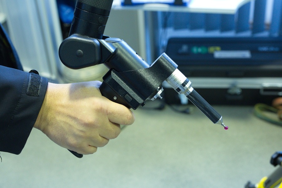
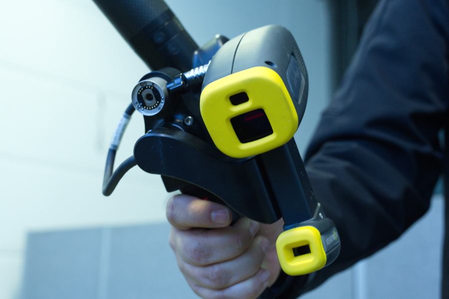
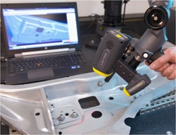
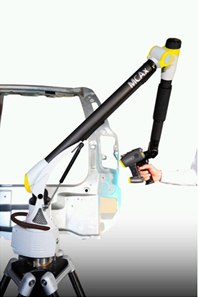
Measuring arm
MCAx measuring arm with scanning head MMDx100:- Measurement range: 2 m
- Point repeatability: +/- 30 um
- Capacity accuracy: 42 um
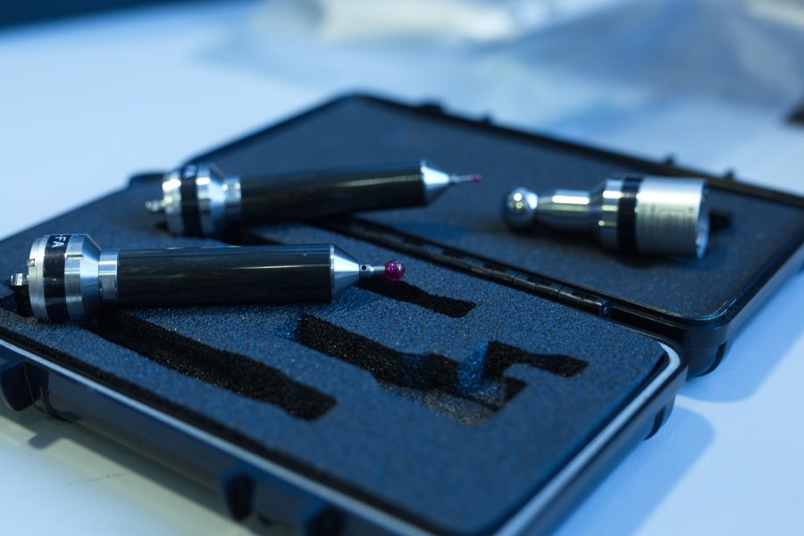
- Measurement probes: 15 mm, 6 mm, 3mm
- The device is fitted with a laser scanner (scanning head)
- Max. speed of gathering points, min. 50000 points/s
About us
Our experts
Our trainers are experienced engineers certified in the field of metrology by the leading producers of tools and coordinate machines – Zeiss / AUKOM / Nikon Metrology / DMG.
In addition, they provide consulting services and work as experts for renowned trade periodicals connected with industrial metrology and machining.
During trainings, their main focus is on passing knowledge of the real examples they have encountered in their professional work.
Our trainers are open to all suggestions made by the participants. It is very common that during trainings the group discusses the issues beyond the scope of the standard program that cover specific aspects of the students work.
Completed courses also lead to cooperation between EMT Systems Ltd. and representatives of industrial facilities in the following areas: projects, modernization and commissioning of the machine hydraulic systems and technological lines.
Materiały szkoleniowe
- a textbook: Geometric dimensioning and tolerancing ISO-ASME/GD&T with coordinate techniques compiled by the Engineering Training Center EMT-Systems Ltd. covering the material included in the program of the specific course.
Catering
During each training day, participants receive:
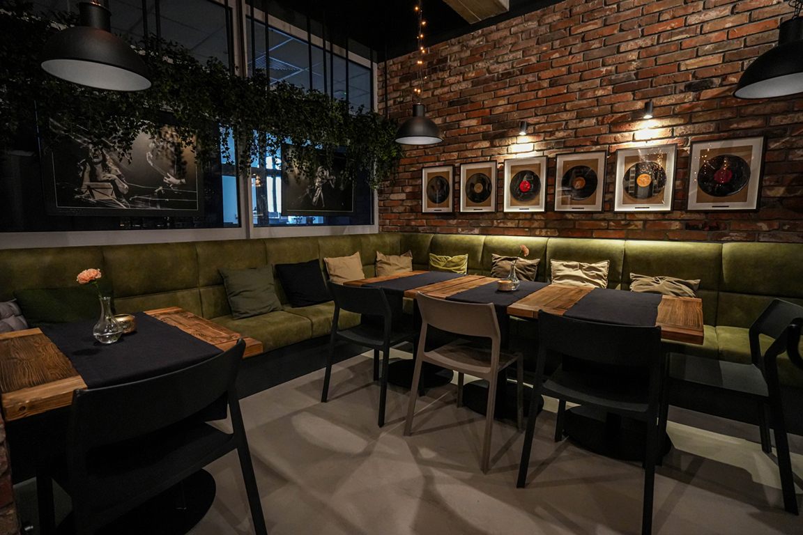
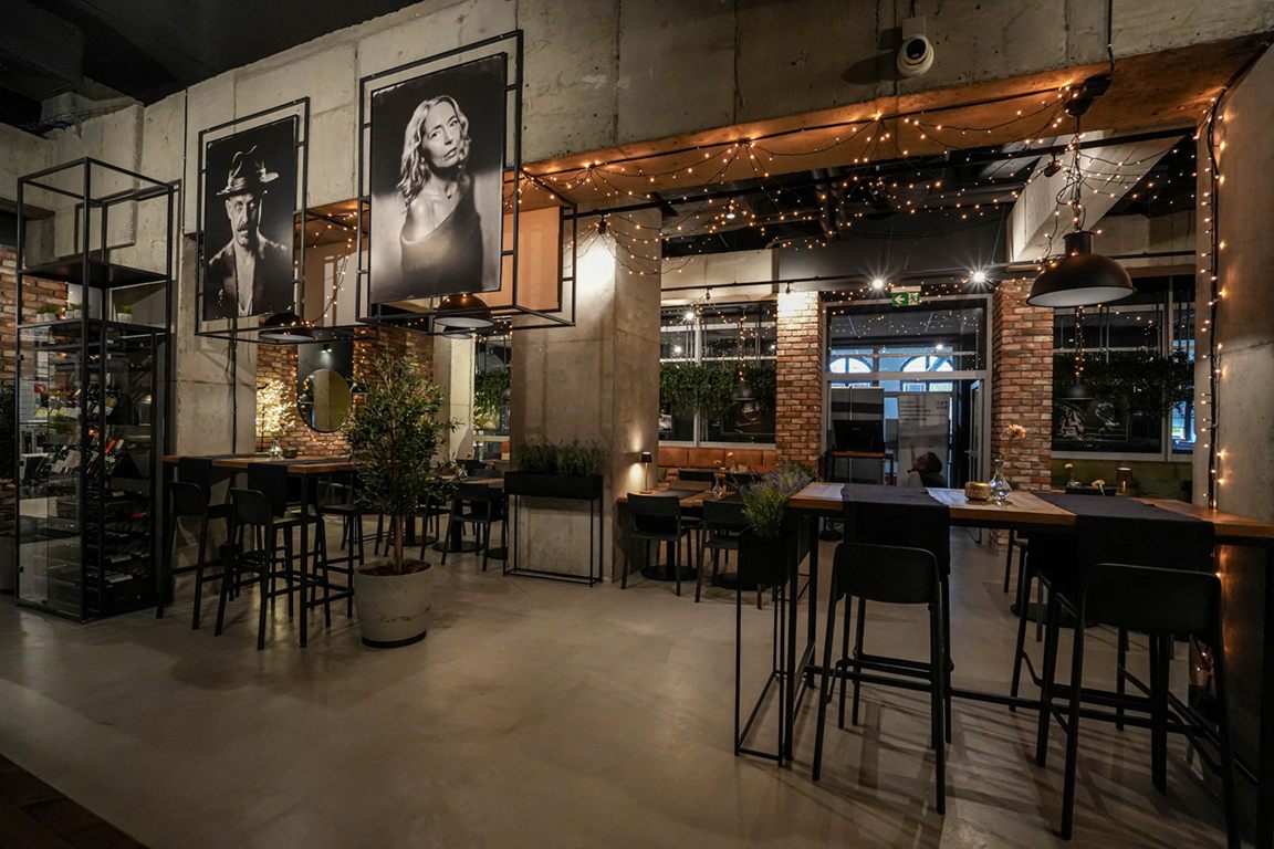
- Unlimited access to the Cechownia Cafe coffee bar, serving tea and high-quality freshly ground coffee. The bar is equipped with:
- NECTO Karisma - a professional espresso machine of Italian production.
- THERMOPLAN BW 4 - a professional espresso machine made in Switzerland.
- Two-course dinner - a combination of traditional, home-made flavors with meals served in restaurants.